- 您现在的位置:买卖IC网 > Sheet目录356 > SC668ULTRT (Semtech)IC LED DRVR LMU 8CH MLPQUT20
�� �
�
�SC668�
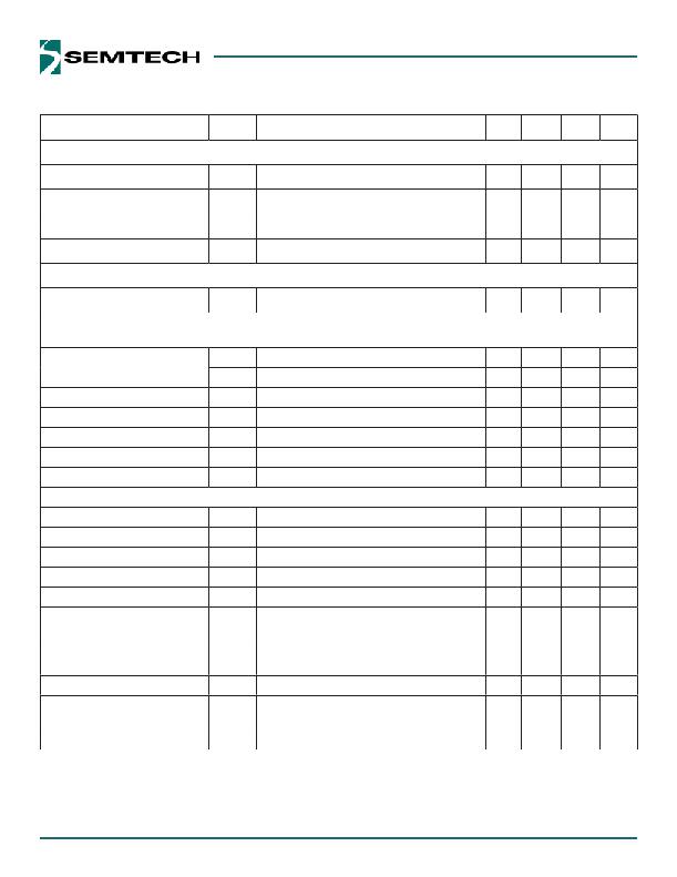
�Electrical� Characteristics� (continued)�
�Parameter�
�Symbol�
�Conditions�
�Min�
�Typ�
�Max�
�Units�
�Digital� Input� Electrical� Specifications� (PWM,� EN,� SDA,� SCL)�
�Input� High� Threshold� (7)� (8)�
�Input� Low� Threshold� (7)� (8)�
�V� IH�
�V� IL�
�V� IN� =� 5.5V�
�V� IN� =� 2.9V�
�1.6�
�0.4�
�V�
�V�
�Input� High� Current�
�Input� Low� Current�
�I� IH�
�I� IL�
�V� IN� =� 5.5V�
�V� IN� =� 5.5V�
�-1�
�-1�
�+1�
�+1�
�μA�
�μA�
�PWM� Input� Specification� (PWM)�
�PWM� Input� Frequency�
�f� PWM�
�0.2�
�50�
�kHz�
�I� 2� C� Interface�
�Interface� complies� with� slave� mode� I� 2� C� interface� as� described� by� Philips� I� 2� C� specification� version� 2.1� dated� January,� 2000.�
�Digital� Input� Voltage� (7)�
�SDA� Output� Low� Level�
�Digital� Input� Current�
�Hysteresis� of� Schmitt� Trigger� Inputs�
�Maximum� Glitch� Pulse� Rejection�
�I/O� Pin� Capacitance�
�V� B-IL�
�V� B-IH�
�I� B-IN�
�V� HYS�
�t� SP�
�C� IN�
�I� DIN� (SDA)� ≤� 3mA�
�1.6�
�-0.2�
�0.1�
�50�
�10�
�0.4�
�0.4�
�0.2�
�V�
�V�
�V�
�μA�
�V�
�ns�
�pF�
�I� 2� C� Timing�
�Clock� Frequency� (7)�
�SCL� Low� Period� (7)� (8)�
�f� SCL�
�t� LOW�
�1.3�
�400�
�440�
�kHz�
�μs�
�SCL� High� Period�
�(7)� (8)�
�t� HIGH�
�0.6�
�μs�
�Data� Hold� Time� (7)� (8)�
�t� HD_DAT�
�0�
�μs�
�Data� Setup� Time�
�(7)� (8)�
�t� SU_DAT�
�100�
�ns�
�Setup� Time� for� Repeated�
�START� Condition� (7)� (8)�
�Hold� Time� for� Repeated�
�START� Condition� (7)� (8)�
�Setup� Time� for� STOP� Condition� (7)� (8)�
�Bus-Free� Time� Between�
�STOP� and� START� (7)� (8)�
�t� SU_STA�
�t� HD_STA�
�t� SU_STO�
�t� BUF�
�0.6�
�0.6�
�0.6�
�1.3�
�μs�
�μs�
�μs�
�μs�
�Interface� Start-up� Time� (7)� (8)�
�t� EN�
�Bus� start-up� time� after� EN� pin� is� pulled� high�
�900�
�μs�
�5�
�发布紧急采购,3分钟左右您将得到回复。
相关PDF资料
SDIN2B2-8G
IC INAND FLASH 8GB 169FBGA
SDK-DM3730-10-256512R
KIT DEV ZOOM FOR AM/DM37X
SDK-DM3730-20-256512R
KIT DEV ZOOM FOR AM/DM37X
SE162216
ENCLOSURE ASSY 6U X 19" X 16"
SF-2194
RACK SWING FRAME 38"X21.25" BLK
SF-2294
RACK SWING FRAME 35" X 19"
SFD1200-12BG
FRONT END DC/DC 1200W 12V
SFH21-PPPN-D07-ID-BK-M181
CONN RECEPT 14POS 2MM IDT GOLD
相关代理商/技术参数
SC-67
制造商:JIFFY 功能描述:CORRUGATED BOX DW 24X18X18 PK15 制造商:JIFFY 功能描述:CORRUGATED BOX, DW, 24X18X18, PK15
SC6750
制造商:Alltrade Tools LLC 功能描述:COMB. SET
SC68253LK081
制造商:ON Semiconductor 功能描述:
SC68253PK073
制造商:Rochester Electronics LLC 功能描述:- Bulk
SC68254DW154R2
制造商:Rochester Electronics LLC 功能描述:- Bulk
SC68254PK4538
制造商:ON Semiconductor 功能描述:
SC68255DWT373R2
制造商:ON Semiconductor 功能描述:
SC68285PK195A
制造商:ON Semiconductor 功能描述: